Configuring GPIO
The GPIO.project project contains an application with free GPIOs with a device editor where the I/O image is configured. The digital inputs and outputs are also defined there.

In the device editor, below the GPIOs I/O Image tab, a DWORD variable is declared for the each of the inputs and outputs. The Bit<X> contains the value of GPIO<X>.
In the example, GPIO18 was defined as an output. It is assigned with a flashing signal in the PLC_PRG program. The visualization displays the value of the inputs and allows for setting the outputs.
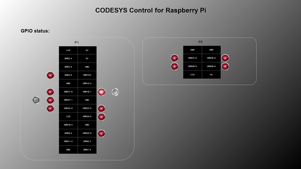
There is a separate, extended device description for the Raspberry Pi B+ model variant. In order to use the GPIOs B+/Pi2 device description instead of the GPIOs A/B, click in the context menu and select the GPIOs B+/Pi2 device type in the dialog.
Tip
Depending on the loaded drivers, some GPIOs may be permanently assigned to other functions and therefore not available.